|
Adding ST1100P (Police) Switches to a VFR
The Problem
VFRs are multi-use motorcycles; some people use them as comfortable sports missiles, others load them down with luggage and accessories and (attempt) to achieve an elusive "fighter-bomber-cargo plane" degree of agility and utility. VSource.org caters to the latter tendency... As quixotic as such a pursuit may be, well, there you have it.
The addition of extra lighting and electrical function to the VSource.org VFR750FP presented both an aesthetic as well as a practical difficulty: Where to put the switches required for, inter alia, driving/fog lights, auxilliary light functions, fan override and hazard lights. In addition to mounting the switches, a separate problem was even being able to find appropriate swithes for the harsh, exposed environment of a sport-touring motorcycle. Fortunately, function does not need to be f-ugly; the solution to the aforementioned problems—without the need to drill holes in expensive plastic or to hang incongruous brackets from existing components—is no further away than your friendly Internet Honda dealer...
A tip from an ST1100 (Pan European)-riding friend led to a lengthy Internet trawl, which turned up few (a very few!) good photos of handlebar switch pods on Police-model ST1100s. Surprisingly, and despite the availability of second-hand ex-police Pans in regions where such bikes are routinely used in many work-related capacities, the retro-fitting of police-spec switches doesn't seem to be a common practice even among "civilian" Pan European riders. Given their (even more serious?) predisposition towards ladening their bikes with lights and various other electrical gizmos, this is somewhat surprising. Anyway, as a result, the part number of the police switch pod had not been previously readily available.
Fortunately, there are online sources of this information (see, e.g., Bike-Parts.fr for a very complete set of European Honda microfiches—with part numbers if you View the Source code...), and Internet-friendly Honda parts sources (try David Silver Spares in the UK—who deliver throughout the world). It appears that the Honda part number for the police switch pod (35150-MZ9-900) is common to all UK-spec police-model Pans from (at least) 1993 through 2000; if the price of a brand new switch is too much to bear (£35 + VAT from David Silvers), ex-police Pans sometimes show up in specialist motorcycle breakers, such as Force Motorcycles in the UK.
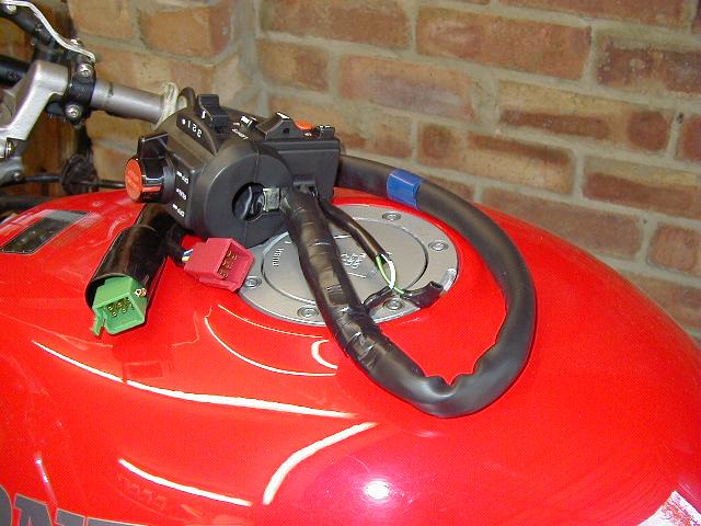
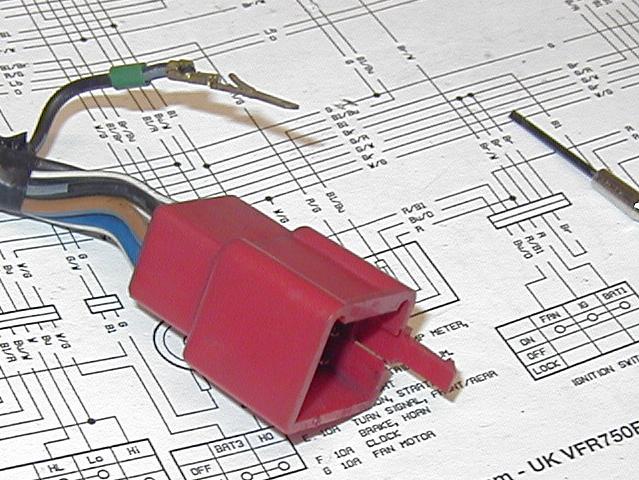
The SolutionSo, what do you get? As shown in the photo below, the police switch pod includes an extra pigtail with a green 9-pin connector (plus one additional wire attached to a male bullet connector) in addition to five new switch functions:
Although the colors of some of the wires may be different, functionally, the red connector has almost exactly the same pin-outs as the original UK-spec VFR Honda connector, but the positions of two wires on the new connector must be swapped (see below). (US/Canadian-spec VFR owners should note that the starting switch is different on bikes with always-on headlights: yours is a "make + break" switch, while it is "make only" on ROW bikes—as well as on police ST1100s. As a result, this swap may not work unless you find a work-around...)
The five additional circuits on the police switch pod are as follows:
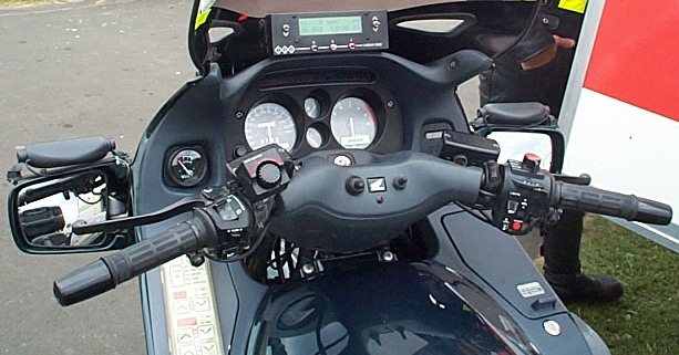
The switch pod fits eerily perfectly onto a standard VFR750FP clip-on; with the brake lever moved as inboard as possible, there is just enough extra room to accomodate the extra width of the police switch unit (~13mm)--even the locating tab that fits into a small hole in the handle bar fits neatly into place. (Please note that the VSource.org VFR750FP uses a front brake master cylinder from a CBR900RR/VTR1000F; this swap has not been tested on a standard VFR.) However, there is an issue with the additional length (depth?) of the switch pod in relation to the VFR fuel tank. Fortunately, this can be solved fairly easily, either by removing the removable locating tab from the new switch pod and rotating the pod back towards the rider, or (preferably) by drilling a new indexing hole in the bar and rotating the pod as above. The result is a switch pod not quite as "upright"as it would be if mounted on a Pan European, but, then again, neither is the VFR's riding position!
The DetailsThe photo above shows the ST1100 police switch pod being used in conjunction with a Vista-Cruise throttle lock. This is slightly misleading, because, with the pod rotated back towards the rider, the Vista-Cruise contacts the VFR fuel tank when the handle bars are turned fully to the right. The normal mounting position for the Vista-Cruise is barely adequate as it is to avoid interfering with (and damaging) the tank, so the throttle-lock really has to be modified somehow or replaced with something else, e.g., a Throttlemeister.
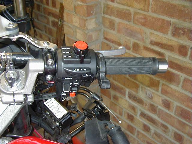
Another drawback relates to the "Engine Stop" switch on the top of the switch pod, which is much more prominent than on a normal Honda switch pod. Due to its size and location, it appears that it will be much easier to operate inadvertently than the original switch—a potentially annoying or even dangerous consequence. There is also a slight theoretical drawback in having auxilliary switches on the RHS switch pod, as opposed to the LHS, in that the left hand is usually much more free to operate such things during a ride. However, these potential configuration drawbacks haven't presented a huge problem to thousands of serving police motorcyclists, so...move along!
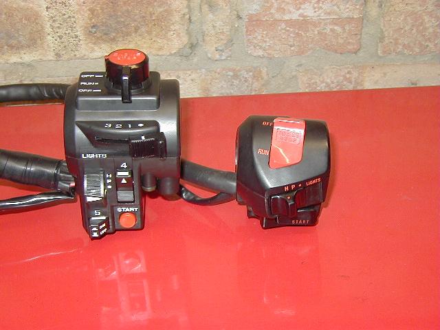
The photo below shows the difference in size between the Police RHS switch pod (66mm wide) and the OEM one (53mm wide):
In order to make use of the additional switches, an additional "Hitachi-type" 9-pin female connector is required (or some sort of bodge!); Honda OEM-style connectors and pins are available from at least these three online sources in the U.S.: The Electrical Connection, California Sport Touring, and Cycle-Re-Cycle. In addition, Vehicle Wiring Products Ltd. in the U.K. stocks replacement male and female pins, but apparently not the connectors. (Note: the 5mmx35mm screws that hold the switch pod together are not included with the unit.)
The following table shows the pin-outs for the new (green) 9-pin connector and how they relate to the switches in the switch pod:
| Switch & Circuit | Function | Connected in Position(s) | Wire Color(s) | Connector Position |
|---|---|---|---|---|
| main switch, circuit 1 | locking | 1, 2 & 3 | light green | (separate bullet) |
| main switch, circuit 1 | locking | 1, 2 & 3 | white | top left |
| main switch, circuit 2 | locking | 2 & 3 | blue | top middle |
| main switch, circuit 2 | locking | 2 & 3 | green/yellow | center |
| main switch, circuit 3 | momentary | 3 | green | bottom middle |
| main switch, circuit 3 | momentary | 3 | orange/black | bottom right |
| rocker switch, circuit 4 | locking | 4 | orange | middle right |
| rocker switch, circuit 4 | locking | 4 | black/blue | top right |
| push-button, circuit 5 | locking | 5 | pink/black | middle left |
| push-button, circuit 5 | locking | 5 | red/orange | bottom left |
(Note: In the table above the orientation of the male connector is with the pins facing you and the locking tab to the right.)
The ModificationsAs noted above, the two wires that need to be swapped are the adjacent black/white (black with white stripe) wire and black/yellow (black with yellow stripe) wire on the ST1100 Police red connector. This is done most easily with a small, jewlers' screwdriver, as shown in the two photos below:
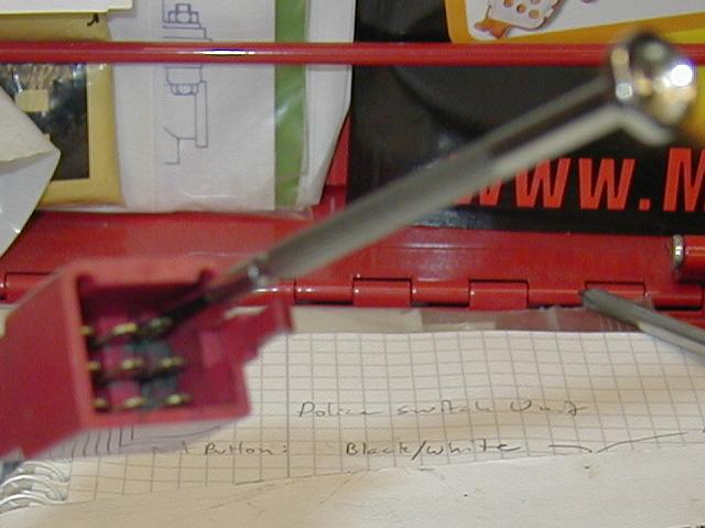
The connector shown in the two photos above is actually the VFR connector, not the ST1000 connector, so you will notice that the wires have slightly different colors, but the procedure is exactly the same. The trick is to insert the tiny screwdriver firmly above the connector you want to release from the housing, depressing its barb, which you can see in the second photo. A little wiggling and pulling ought to free it—sometimes you have to remove the screwdriver before it will pull out. Before re-inserting the connectors, into their new positions, pry the barbs back up so that the connectors won't back out again. That's all there is to it!
The PossibilitiesWhat you choose to control with the new switches is, of course, entirely up to you, but here's what they're being planned to be used for on the official VSource.org VFR837FP:
| Switch & Circuit | Function | Connected in Position(s) | Connected to... |
|---|---|---|---|
| main switch, circuit 1 | locking | 1, 2 & 3 | Fog Lights |
| main switch, circuit 2 | locking | 2 & 3 | Driving Lights |
| main switch, circuit 3 | momentary | 3 | [...er, siren?] |
| rocker switch, circuit 4 | locking | 4 | Hazard Flashers |
| push-button, circuit 5 | locking | 5 | Fan Override Relay |
| Copyright © VSource.org 1999-2005 [Source: Thanks for the idea, Mike!] |